Get Natural Gas Plant Process Flow Diagram UK. Conventional natural gas combined cycle ngcc process. Process flow diagram for the regeneration column portion.
Its process flow diagram is shown in figure 1.
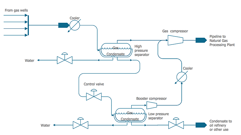
Figure 1 shows a simplified block flow diagram (bfd) of a methanol (meoh) plant based on coal feedstock. Syngas from the gasifier is cooled by generating high pressure (hp) steam in the high temperature (ht) gas cooling system before being water quenched and scrubbed to remove fine. Process flow diagrams are widely used by engineers in chemical and process engineering, they allows to indicate the general flow of plant process streams and equipment, helps to design the petroleum refineries, petrochemical and chemical plants, natural gas processing plants, and many. The cooled fuel gas is then passed through the conventional h2s.